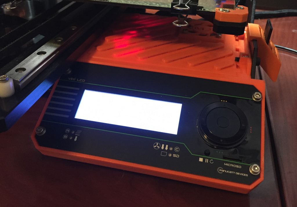
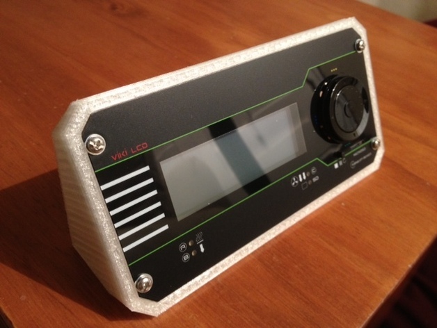
Still playing catch-up with the updates. But here we go. First up, got the VIKI LCD working, after scouring the web on how to get this wired up with the azteeg x3 + marlin. The buttons all seem to do the same thing, but the encoder works, and the display works. It appears the support in marlin is minimal so this isn’t so bad.
Next I got the Helios heated bed mounted. The parts from panucatt shipped with some good insulation to stick underneath of it. So did that part.

Then I cut some glass, I found a glass cutter and a sheet of replacement glass for picture frame. Cut it down to about 8×8. This was my first time cutting glass so I’ll most likely buy another one and do it again, as I cut it a little too short. After I was done cutting I sanded the edges with sandpaper just to keep myself from bleeding all over the place.
I know everyone loves binder clips, but this is all I had, so I’m using these clips for now until I get some binder clips. The binder clips don’t stick out as much so I do want to do that. Here’s the board mounted.
At this point I mounted all the limit switches and wired them up. It appears to me most people building these mount the z home switch towards the bed. I feel like that is an odd thing to do, because you will constantly have to tweak that so people make a mount with a screw so they can finely dial it in. I remember using the Makerbot Thing-O-Matic and it homed it’s z on the limit then in software knew its height and could be set via software. So I went that route. I mounted the Z on the limit, then I set the height via repeteir and it knows where 0 is based off of that. This way I can tune it into fractions to get the z where I want without physically tweaking something.
From there it’s just twist more wires, and fire it up. I’m actually amazed at how long the bed takes to heat up. I have the thermistor snugly against the glass in the center so I’m reading the glass temp. But it takes quite awhile to warm up. I think I’m going to throw down some transistor grease between the glass and the bed to see if that improves. For now we will go with it.
There it is folks. The first print. Obviously I didn’t set my extrusion rate properly. So cancel that. And lets try again.
And boom. Now that’s a pretty print. Yeah I know it’s lopsided. That was because I actually didn’t tighten the belts before I started. So I was tightening them while it was printing. Otherwise it’s a great looking print for #2.
Now that everything is working properly, it’s time to fix the wires, and then I can go back to dialing in that picture perfect print.
Home›Repetier-Firmware›Tips & Tricks
Viki Lcd I2c
LCD Contrast i2C Pull up Short to enable (Dis-abled by default) Buzzer mSD SLOT PUSH SWITCH 20X4 LCD mSD ACTIVITY LED HEAT BED LED EXTRUDER 2 OR FAN LED EXTRUDER 1 LED viki lcd UP DOWN LEFT RIGHT SELECT ROTARY ENCODER (RED)+5V SDA ENCB GND SCL ENCA CS DI CD BTN CLK D0 J2 J3 +5v - +5 Volt supply, requires about 120milliamps for LCD and mSD.
- It also includes a 3D printed enclosure for the display and all the cables you need to connect it to the Rambo board in the M2. I think it was worth it seeing I didn't have to go to multiple sources to acquire parts and I don't mind giving $$ to Makergear seeing they've been good to me over the years.
- Follow this tutorial to replace the VIKI LCD screen on the AXIOM Series 3D printers. Contact us at www.airwolf3d.com for more information.
- LCD Contrast i2C Pull up Short to enable (Dis-abled by default) Buzzer mSD SLOT PUSH SWITCH 20X4 LCD mSD ACTIVITY LED HEAT BED LED EXTRUDER 2 OR FAN LED EXTRUDER 1 LED viki lcd UP DOWN LEFT RIGHT SELECT ROTARY ENCODER (RED)+5V SDA ENCB GND SCL ENCA CS DI CD BTN CLK D0 J2 J3 +5v - +5 Volt supply, requires about 120milliamps for LCD and mSD.
- The problem is that with some 3D printers, the Viki2 will cause the printer to 'pause' every time the LCD display updates, which is normally every second. This is not only annoying, but tends to ruin your print since your filament still flows while the print head suddenly stalls.

Lcdp Viki

Viki Lcd Controller
Wiki Lcd Display
Viki 2 Lcd
Comments
Viki Lcd
- Thanks for the contribution. I have put it in the sources for next update as there is now a official pinout for ramps. When I wrote it the support files did not contain it I think.The red button is for reset pin, but I do not see a reset pin on ramps board.
